

Beskrivning
IPJ-A5000-000 Anslutningsbox för digitala IN-UTgångar till Impinj Speedway Revolution läsare
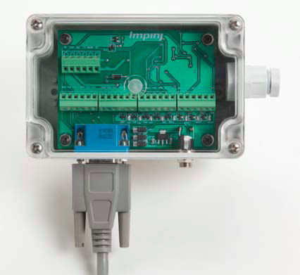
Impinj har utvecklat “Speedway® Revolution GPIO Box” för att förenkla kabelanslutningar från periferienheter som givare, signaldon, reläer mm. (GPIO = General Purpose Input and Output)
Boxen ansluts till läsarens mångpoliga GPIO-kontakt med en färdigkontakterad kabel. Ledningar från givare, signaldon, mm ansluts på kopplingsplintar i boxen.
Features
• Easy-access screw terminals
• Power and ground terminals for each input and output
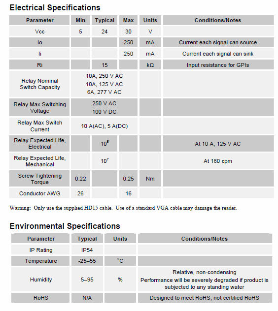
• Each output can provide 250mA at 24V with optionalexternal universal power supply
• SPDT Relay output capable of 5A at 240VAC
• Ability to use reader-supplied 5V for low power digitalapplications, including the SPDT Relay
• Highly visible LED indicators for each input andoutput eases troubleshooting and diagnostics
• Access to reader’s RS-232 serial interface
Example Application Scenarios
Connecting an Allen-Bradley Sensor
An Allen-Bradley 42CM PNP laser sensor can be quickly and easily connected to the Speedway Revolution GPIO
Box using the A-B 889D connecting cable:
1. Unplug the power and reader connection cables from the GPIO Box.
2. Remove the clear, plastic cover using a screwdriver.
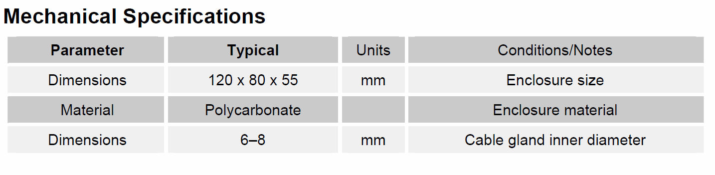
3. Loosen the cable gland and insert the bare wire ends of the cable into the GPIO Box.
4. Connect the brown wire to a Vcc to the right of the input you wish you to use and tighten down the screw.
5. Connect the Blue wire to GND to the left of the input.
6. Connect either the black or the white wires to the input terminal you wish to use. (The black wire associates to the Light Operate mode of the sensor and the white associates to Dark Operate.)
7. Tighten the cable gland to cinch down on the cable.
8. Replace the clear lid and plug the reader and power cables back into the GPIO Box.
Use the Multi-Reader application to verify that the sensor is working correctly, and triggering on the designated markings.
Power Low Wattage Light Signals
In many applications it is helpful to utilize a light stack to indicate the status of an RFID system. By using the four GPO Outputs of the Speedway Revolution, an application can turn on or turn off different lights depending upon which antenna is operating, if the reader is currently writing tags, or if it has encountered an error while writing.
You may connect LED or low wattage (less than 6 W) lights directly to each OUT signal and either the neighboring GND or Vcc depending upon whether you want the light to turn on when the GPO is high or low. Or, connect two lights to the same signal by connecting one to Vcc and the other to GND. In this case, when the GPO signal is high, one light turns on and when the GPO goes low, the other light will turn on.
Power High Wattage Devices and Using the Relay
By using the on-board relay, you can interface to, and control high wattage devices.
To use the relay, simply move the top jumper, labeled JGPO, on the GPIO Box board to the left two pins, labeled RLY and RO1. This action connects the GPO1 signal from the Speedway Revolution to the control circuitry for the relay.
You can then connect the device with which you wish to interface to the three terminals on the top left of the board. One connection will always be connected to the COM, or common, connection. The other two connections will be either a short to COM or an open, depending on the value of GPO1. If GPO1 is low, then NC (normal closed) is shorted; when GPO1 is high, NO (normal open) is shorted.
To power a high wattage light, connect COM to ground and NO to one terminal of a light. The other terminal of the light should be connected to an appropriate power source.
When GPO1 is low, NO will be an open circuit and will not allow the light to turn on. When GPO1 is high, it will short NO to ground and turn on the light. The relay can be switched even while using the 5V supplied by Speedway Revolution.
Note: when using the relay, OUT1 signal will no longer operate and will always output as a high signal.
Using Speedway Revolution’s 5V Supply
A feature of the Speedway Revolution is the 5V supplied through the GPIO port. By using this power supply, you may provide a power source to low-power logic devices without requiring a separate power supply. To utilize the 5V supply from the reader, move the bottom two jumpers to the left two pins. In this configuration, the row labeled Jplus should have the jumper connecting the pins labeled 5V and Vcc. The row labeled Jminus should have the jumper connecting the pins labeled RGND and GND.
Note: when using the reader’s supplied power source, the opto-isolation built within Speedway Revolution is bypassed, which may cause signal degradation.


